
Last Updated: 12 February 2024
How To Wire a Peco SL-E383F Electrofrog Scissors Crossing for DCC
Check out our downloads page for printable Peco Track Templates and drilling guides for baseboard wire routing.
Overview
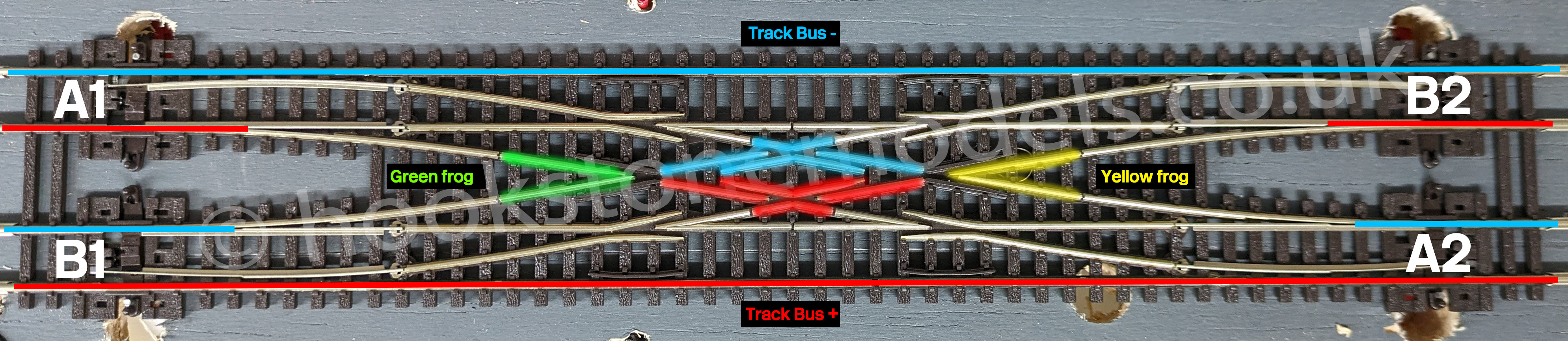
This scissors crossing comes with four bare metal 'tails'. They provide power to each of the four 'zones' in the middle of the crossing, which are marked on the diagram below in blue, red, green and yellow. If you look closely, you will see that these pieces of rail are isolated from their surroundings with small black pieces of plastic. The polarity of some of the rails in the central section are omitted from the diagram to make it easier to see what is going on.
This guide shows you how to wire up this scissors crossing for DCC, using four MTB MP1 point motors. These small point motors are quiet and have a more realistic slow-moving changeover. They also draw only a small current when moving (150 mA) and have end-of-travel switches which automatically cut the power once the point has fully moved across. The MTB MP1 point motor provides built-in frog polarity switching, which means no additional 'frog juicer' or similar electronics are necessary.
Step 1 - Connect Blue & Red to Track Bus
The blue and red 'zones' are always the same polarity regardless of the route set, and match those of the very outer fixed rails. As such, these can be wired straight into your track bus. On the diagram, these are notionally designated '+' and '-' because it's easy to understand. As the tails are bare metal, it's a good idea to cut them back and solder a wire onto the end, with a piece of heatshrink sleeving over the joint.
Step 2 - Solder Wires to Green & Yellow Frog Tails
The green and yellow 'zones' look more like the normal 'V'-shaped frog on conventional points. Just like conventional frogs, these need to change polarity depending on which route is set. As per the previous step, cut the tails back and solder a wire onto each, applying a piece of heatshrink sleeving over the joint.
Step 3 - Fit Point Motors
Fit the four point motors to your baseboards, and connect the COM, Poz1 and Poz2 terminals on each to your accessory decoder. We have used a Digikeijs DR4018 which has been pre-programmed to switch eight MP1 point motors using our online Digikeijs DR4018 CVV Programming Calculator.
Connect the track bus power to the top two terminals on the MP1 motors, this should leave just the Aux1 terminal free, which is for the frog wires.
Step 4 - Connect Frog Power
Connect the Aux1 terminal of motor A1 to the green frog. Connect the Aux1 terminal of motor A2 to the yellow frog. At this point you can check that everything is correct with a multimeter. When A1 is set to diverge, the green frog should be connected to the red track bus. When B1 is set to diverge, the green frog should be connected to the blue track bus. It follows, then, that if A1 and B1 are both set to diverge, you will get a short.
When B2 is set to diverge, the yellow frog should be connected to the red track bus. When A2 is set to diverge, it should be connected to the blue track bus. Again, if A2 and B2 are both set to diverge, you will get a short.
This wiring configuration works because of the assumption that you will never set the paths so that trains can cross between A1-A2 and B1-B2 at the same time.
Advanced Configuration
To help avoid shorts and invalid routes - and also to save some outputs on your accessory decoder - you can connect pairs of point motors e.g. 'A1'/'A2' to the same decoder output. That way, opposite points are always both set to straight or diverge. Do the same for 'B1'/'B2'. Note that your accessory decoder will need to provide sufficient power to achieve this, and is not recommended for solenoid type motors, or others that draw high power.