
Last Updated: 27 October 2024
Beginner's Guide To DCC Conversion
How DCC Works
Analogue (DC) locos work by directly connecting the power coming from the track rails, via the wheels, to the motor. The speed is governed by the amount of voltage the controller is putting into the track: the higher the voltage, the faster the train goes. In simple terms, this arrangement effectively means only one locomotive can be present on the track at any given time.
In a DCC layout, the track is permanently powered - usually to between 12 and 16 VAC. The motors are no longer connected directly to the track, but instead via a DCC decoder. It is this device that takes the AC current from the track, and decides what DC voltage (if any) should be sent to the motor. The way it makes this decision is from commands that are sent to it from the command station, which are encoded over the track's AC voltage. Brian Lambert has a more in-depth explanation.
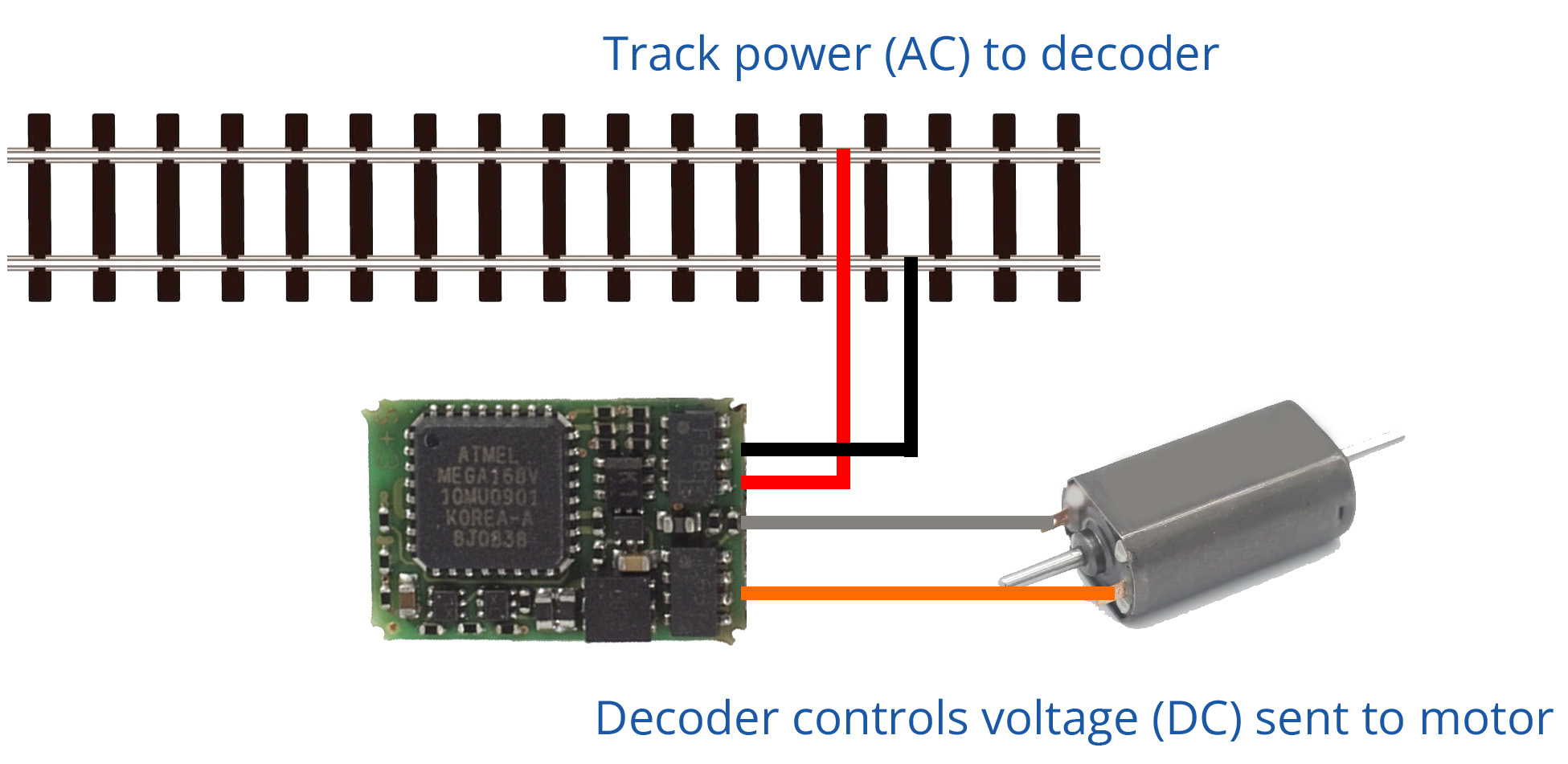
This system allows multiple locomotives to be on the same track, and to be independently controlled. As the track is permanently powered, it also simplifies powering things such as coach interior lighting which can remain at a constant brightness even if the train is at a complete standstill.
Many modern locos are supplied 'DCC Ready', with a socket somewhere inside the body for a DCC decoder to plug straight in. For older or non-DCC ready examples, some modification is required. The effort required varies depending on the chassis style, particularly where parts of the chassis are 'live', i.e. used as part of the track-to-motor power circuit.
Converting DC Locos to DCC
It is possible to convert non-DCC compatible locos to DCC. The basic process is always the same:
- Test that the loco runs well on a DC layout
- Isolate the motor contacts from the track pickups
- Wire a DCC decoder to the track pickups
- Wire the motor to the DCC decoder
- Find somewhere inside the body to hide the decoder
It is important that the loco runs well in both directions before attempting a conversion. Poor runners do not lend themselves well to DCC.
Due to the size of N Gauge locos, the smallest decoders are usually the best choice as space can be limited. In some older steam locos, it is possible to hide the decoder inside the tender. For smaller locos, there is often no option but to either mill away some of the chassis/body to make room, or to simply put the decoder on the footplate and accept that it won't be as aesthetically pleasing.

Most conversions follow a similar pattern, so we have put together some general guides for each chassis type. For extra clarity and as a reference library, we have also added photograhps of many specific conversions that we have carried out. These also cover models that require specific steps to convert them.
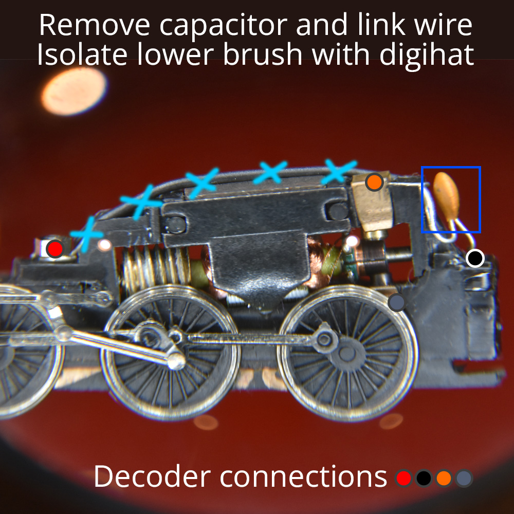
Graham Farish Brass Sleeve
Many older Graham Farish steam locos have this chassis style, as well as some diesels and Poole-made electrics. Note the brass sleeves above and below the motor. Inside these sleeves, there is a carbon brush and a small spring. The spring is held in place with a metal clip. The lower sleeve requires replacing with a plastic one so that the lower motor brush can be isolated from the track pickups. We have a page dedicated to the general Digihat DCC Conversion procedure.
Some older models, for example the original Class 90 and Class 91, have two brass sleeves that need replacing due to the way that both the upper and lower chassis sections have continuity with the track pickups, but the Digihat DCC Conversion procedure is a good starting point.
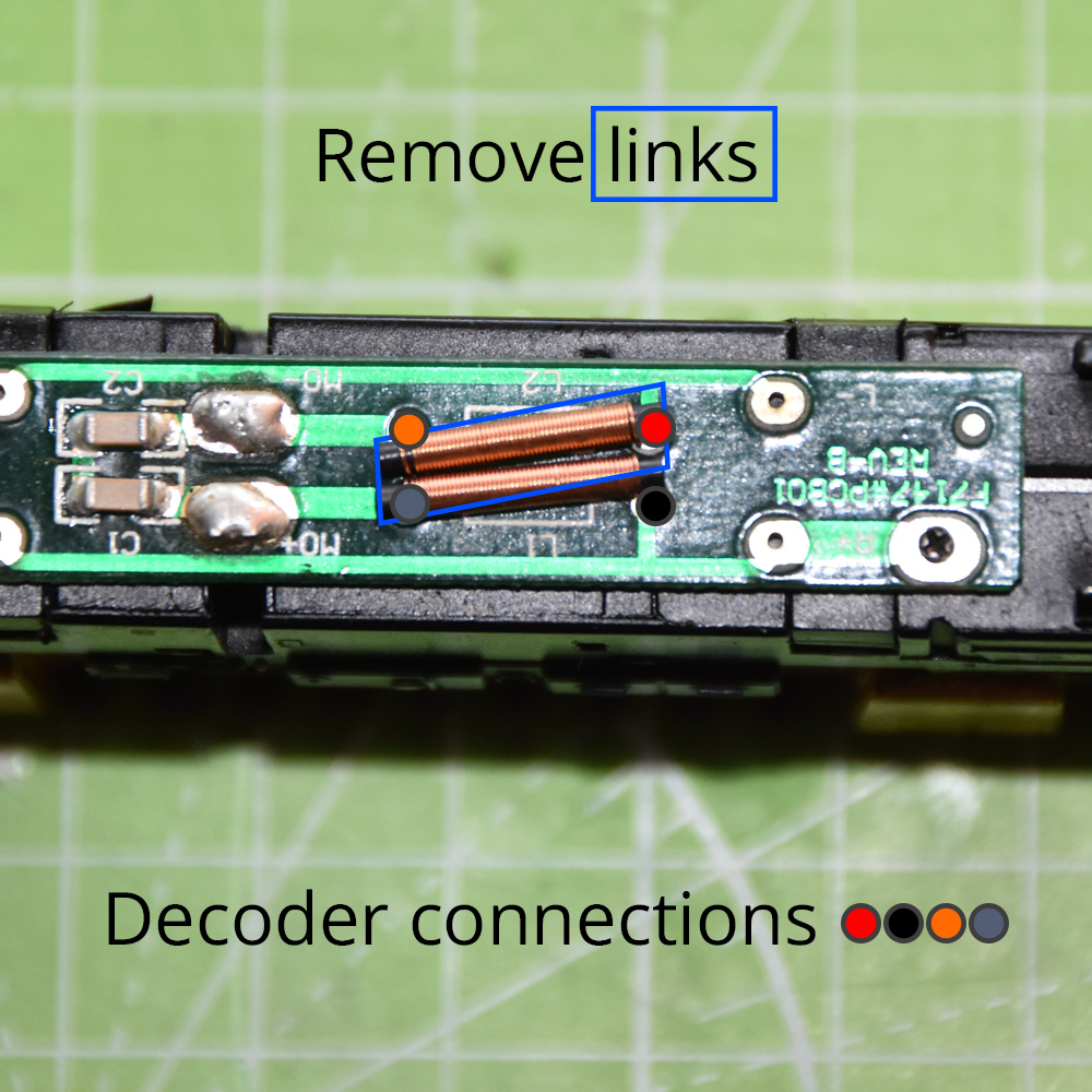
Graham Farish 'DCC Friendly' PCBs
While not having a plug-in socket for the decoder, the more modern Farish locos have a PCB with convenient soldering points for track and motor power. To convert, the link wires between the two sets of solder points needs removing, and the decoder inserting in between.
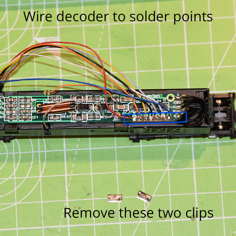
Locos with more complex wiring, such as those with lights, have a PCB with seven solder points. Examples include the Class 60 and Class 66. The solder points are initally bridged using two factory-fitted brass clips to make the loco run on a DC track. Converting these is a matter of removing the brass clips, and wiring each of the seven solder pads to the decoder.
Graham Farish Split Chassis
This chassis type is in two halves, each forming part of the circuit from track to motor. Isolating the motor from the live chassis body halves requires removal of some of the metal using a file or Dremmel style tool. There is also an early version of the split-chassis arrangement which uses the older 5 pole motors, and requires two digihats to convert.
Minitrix Diesels
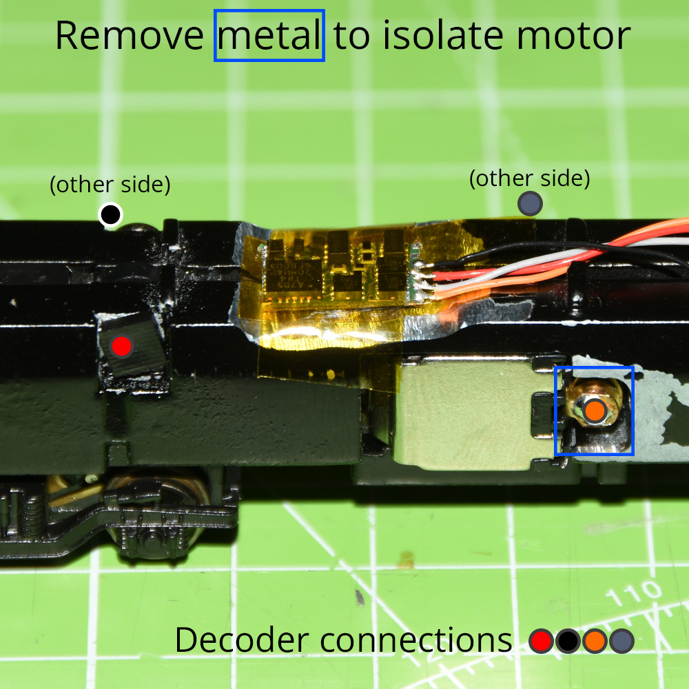
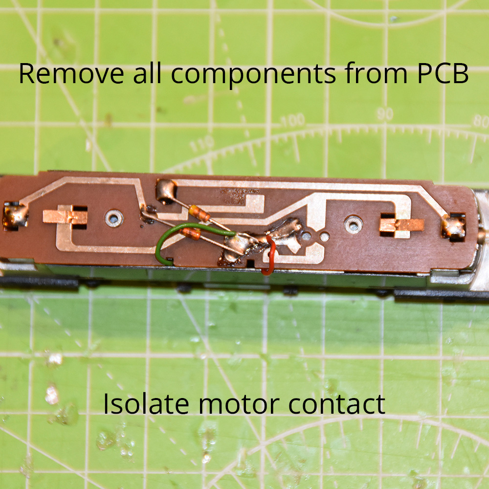
There are a few different arrangements here, and therefore a few different ways of converting to DCC. Usually you will see a smaller lower PCB underneath the motor, and a larger PCB above. Depending on the model, the lower PCB may deal with the track pickup wipers only (e.g. Class 47), or it may also have contacts onto the motor. If this is the case, such as with the Class 27, then some additional modifications are required to isolate the motor contacts.
The model specific pages have details on converting each individual model type.
Minitrix Steam Locos
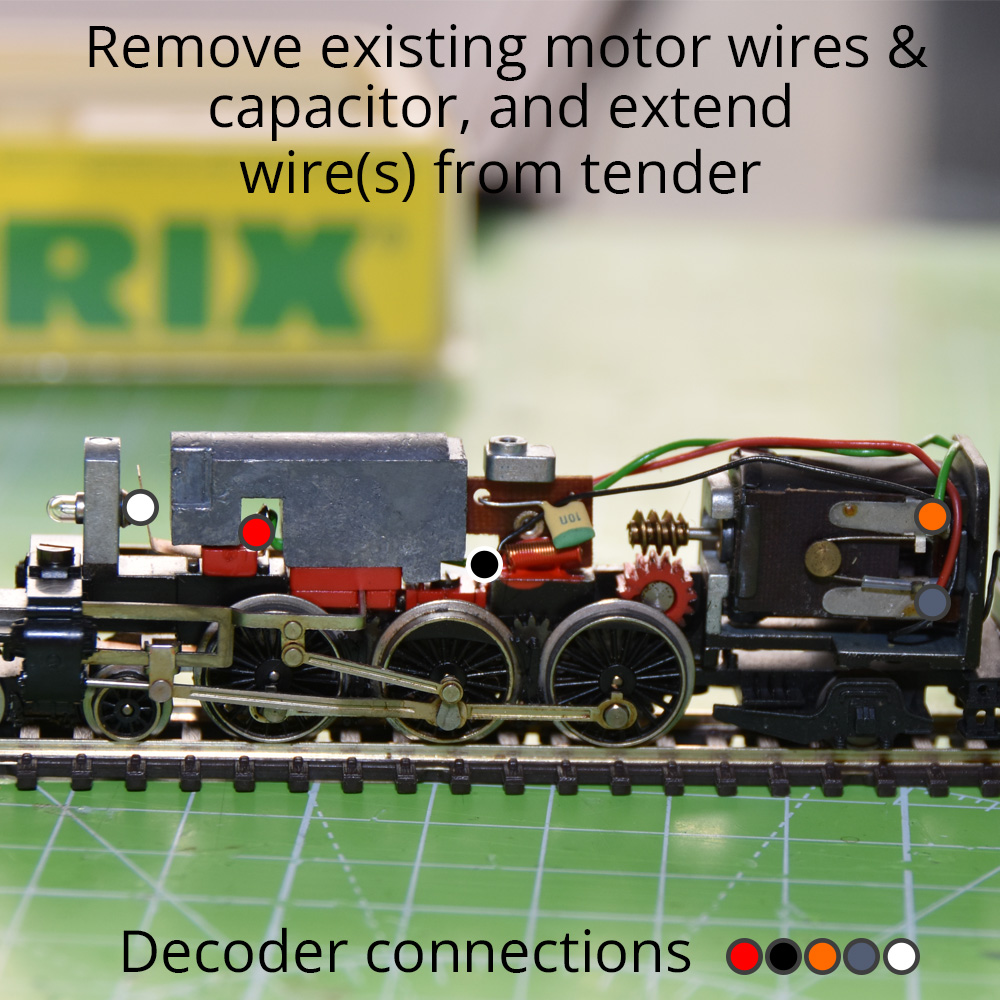
Most Minitrix steam locos follow a similar pattern. There are pickups from the loco wheels and the tender, which both ultimately go directly to the motor. The motor also usually has a metal spring clip underneath it which must be removed to completely isolate it from the chassis. Selected Minitrix steam models also have a light at the front which can also be converted if your decoder supports it. See our guide on Minitrix Steam Loco Conversion.
Where lights have one side connected to the body, you can usually just remove the other connection and connect the white decoder wire instead. If the light is completely isolated from the chassis, you will need to also connect the blue lighting common wire. If in doubt, it's usually best to isolate the bulb or LED from the chassis if possible. Note that it will sometimes be necessary to reduce the output power to the bulb by changing a CV setting, otherwise it will be too bright/hot.
Kato Electric Locos
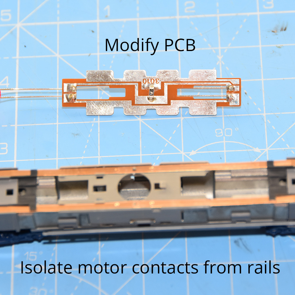
Kato produce excellent N Gauge models of the Class 373 Eurostar and the Class 800. Both follow a similar design, whereby there are two copper strips that run the length of the loco - one for each track pickup. One or more PCBs clip onto these strips to provide the motor and/or lights with power. Kato produce special clip-in decoders for the Class 800 and Eurostar models. The Eurostar DCC PCB still requires some modification and is expensive. Wiring a small decoder directly is the best option and produces excellent results.
With a careful approach and good soldering skills, converting DC locos to run on your DCC layout is eminently possible. Hookstone Models provide a professional DCC conversion service at a reasonable cost, and with a choice of decoder manufacturers to suit your taste and budget.